Project 3: Performance Programming
Project 2.2 Project 3
Introduction
Please read to last years Project 3 description. It was about filling missing pixels in a 3D depth image: Project 3 2016.
This year we are going to continue working with this data. This year the goal is to calculate (something like) the normal of each pixel. In principle the normal vector of a point in a point set means that we fit a plane through the surrounding points. The normal vector is then giving us the orientation of the plane in 3D (2 angles).
To simplify the calculation we will calculate the two angles with respect to (w.r.t.) the polar coordinate system of the scanner - because then we can just work with the pixels of the depth image. As a consequence the normals are always from the view point of the scanner - e.g. if we are scanning from inside a sphere all the normal vectors would point to the sensor and would thus be the same in the polar coordinate system (0 degree deviation from the view axis). This is also why in the example image below the floor doesn't have a unique color - it is gradually changing with more distance to the sensor. In fact we can say that we are calculating the incidence angle of the scanner towards with the surface (normal).
Our result will be the two angles describing the orientation of the plane, in radians. We calculate those two angles based on a number of surrounding points: we use kernelSize x kernelSize points.
Our math is the following:
We calculate the angle in the x-Axis and y-Axis separately. For the x-Axis we use atan( depthDifference / xDistance ) to calculate the angle between two pixels. depthDifference is just the difference in depth between the two pixel. xDistance is the distance in x-Axis between the two pixel if they had the same distance as our center pixel. First we calculate the angular difference between neighboring pixels as stepRad = 2 * pi / 20256 (because our 360 degree image has 20256 pixel). Then we calculate the distance at our point with sinStepDistance = sin(stepRad) * distanceOfPoint. Finally we need to take care that our other pixel might be more than just one pixel away, so we multiply with x: xDistance = x * sinStepDistance.
After taking the atan for all pixels in our area around the main pixel we just average all of them. The calculation for the y-Axis is done accordingly - the same stepDistance between pixels is assumed.

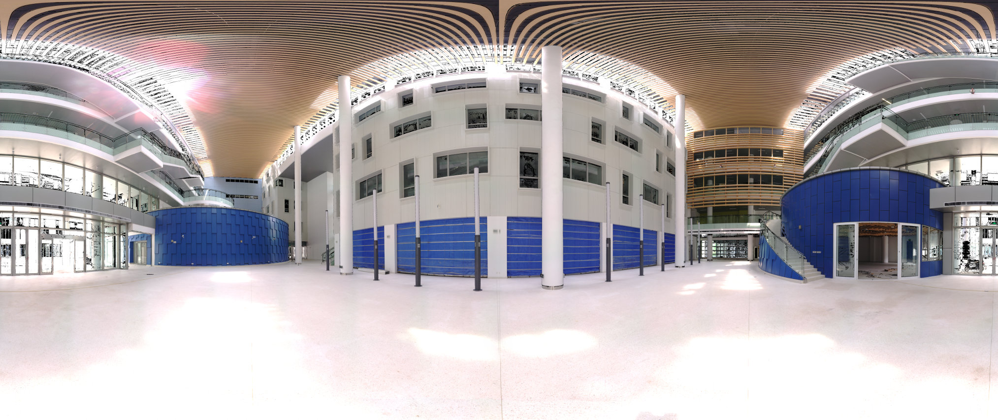
Fig. 1: The scan of the lobby of the new SIST building in color. Full resolution (154MiB).

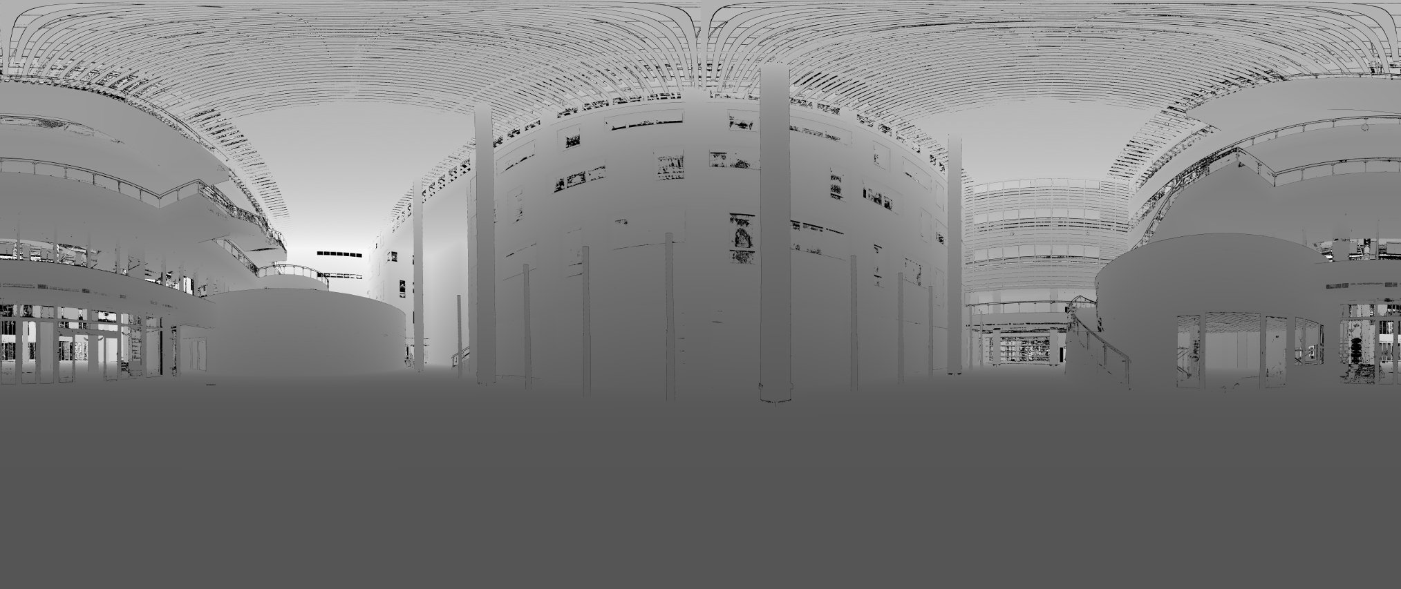
Fig. 2: The depth image of that scan capped at 60m. The darker the closer to the camera. Completely black pixels are error points. Full resolution (7MiB).

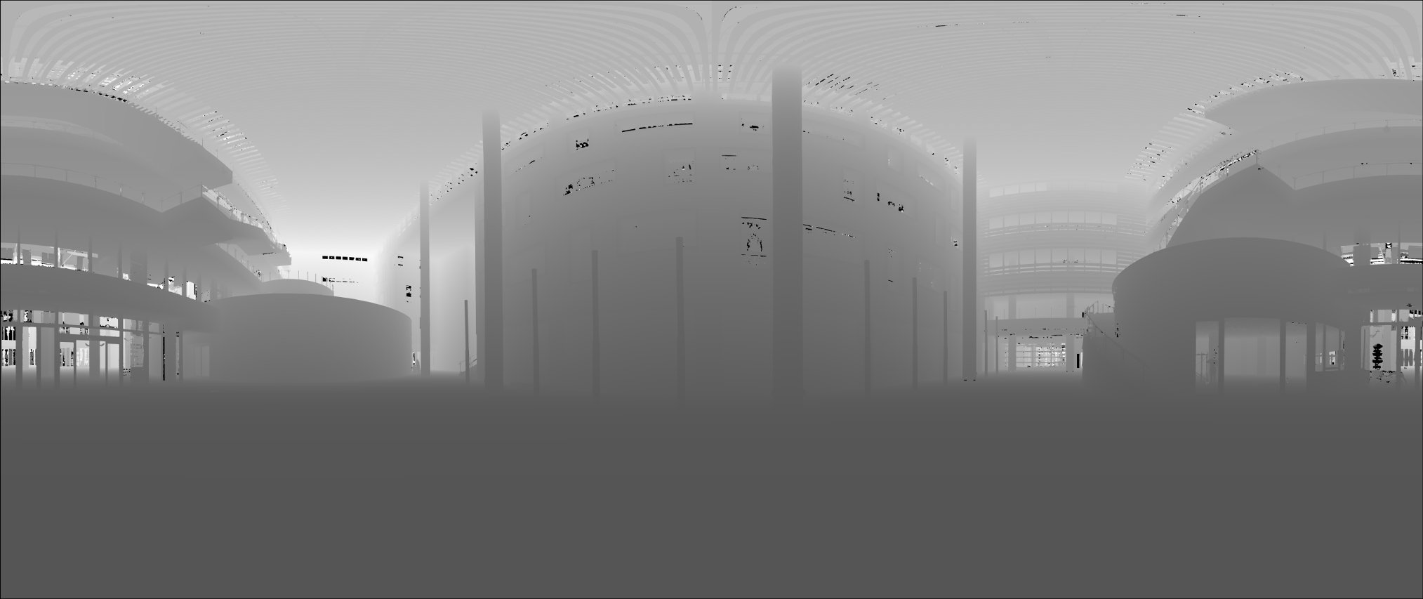
Fig. 3: Depth image where many of the error points have been removed by interpolation (kernel size 15, std. deviation 4). This is from a result from last years project and the input for this years project. Full resolution (7MiB).

Fig. 4: The angles depiced in shades of red for the x-axis and shades of blue for the y-axis. intLobby_15_4.bin was used as input with a kernel size of 5. The computation with the reference program on an i7 MacBookPro took 125 seconds. Full resolution (124MiB).
Also note that both interpolated images have a black "border" around the edges. This is because of the kernel size. A better implementation could still start from the edges, but would then have to perform extra checkings. Also such an improved implementation would need to take care of the fact that the image is 360 degree, the pixel next of the zeroth pixel of a line is the right-most pixel. But we ignore those details for this project.
Reference Program:
- normalsFloatImg.cpp: Reference implementation.
Downloads:
- Input depth map: lobby.bin (660 MiB)
- Output normal map (kernel size 5): intLobby_Normals.bin (1420 MiB)
- Input depth map cropped: cropped.bin (3.8MiB)
- Output depth map cropped: croppedNormals.bin (kernelSize: 15) (7.7MiB)
Tools:
- compareNormalFloatImg.cpp: Compares two binary normals files if they contain the same values, up to an epsilon provided as argument. This program will be used by the gradebot to check if your program computes the correct result. The epsilon used will be generous 0.1 (rad).
- normalImage2png.cpp: Takes a float normal image and creates an according png image for visualization. Depends on libpng and png++ .
- Makefile for all three programs (for Mac - you will need to adjust the png++ location for your system - or comment out floatImage2png).
Task:
In the computer architecture lecture we have learned several techniques to make programs faster. Use them to implement the algorithm as fast as possible. You can change whatever you like - it is only important that your output is the same as the reference program. You may not use any specialized math library - SSE and openMP should be enough.Do NOT set the number of threads of openMP by hand - it will be set by the environment variable!
The simplest approach is to take the reference implementation and start changing/ optimizing it.
You might also gain a good speedup by optimizing the algorithm itself - the allowed maximum error of 0.1 should be quite sufficient for this!
Take care of what makes sense to optimize and what not. For example the reading and writing of the images is not part of the timing - so you do not need to change anything there. Update: The actual grading run later will use a big kernel - maybe 127 or 255 - so make sure you program is compatible with this.
Submission:
Check into gradebot:- normalsFloatImg.cpp: Your fast implementation.
- Makefile: Your Makefile.
Grading
Gradebot will use a small map to test your program. If your output is incompatible you will receive 0 pts! Gradebot will show you the output of your program - keep it short! This way you will have a rough estimate how fast you are compared to the other students. But keep in mind that the gradebot is a shared resource, so those values might differ a lot.The gradebot checking will be implemented within this week.
Your program will be run on a 10 core (with HyperThreading 20) machine, using the 255, 20 parameters, running Ubuntu 14.04. The speed of each program will be noted.
The slowest 33 percentile and below will receive a score of 80%. The fastest 20 percentile will receive a score of 100%. All other programs will get a score that is linearly scaled between those values.
This project is only worth half of Project 1.1, 1.2, 2.1 or 2.2. (This project 11.11%, other (partial) projects: 22.22%).