Faro Scanner Localization using RTK Sensors
Authors: Pingcong Li, Yuezhong Wang
Date: November 2024
Abstract
Point clouds are widely utilized as a 3D mapping format for representing environments with high detail. The Faro scanner is a powerful device capable of generating dense, accurate, and colorized point clouds by integrating LiDAR and camera data. Accurate localization is essential to effectively merge point clouds and construct cohesive maps. This project aims to enhance the Faro scanner's localization capabilities by integrating an RTK sensor, utilizing processed RTK data to achieve precise and reliable positioning.
1. Introduction
Point clouds have become an indispensable tool for 3D mapping, enabling highly detailed environmental representation essential for fields such as land surveying, construction, and autonomous navigation. The Faro scanner, a leading device for point cloud generation, combines LiDAR and camera technologies to produce dense, colorized, and high-resolution data. However, while the Faro scanner excels in capturing spatial information, it currently lacks built-in localization capability, limiting its effectiveness in scenarios where precise positional alignment is required.
To address this, our project proposes to integrate a Real-Time Kinematic (RTK) GPS sensor with the Faro scanner to achieve high-precision localization for outdoor applications. RTK technology, known for its centimeter- or millimeter-level accuracy, enhances standard GPS data by providing real-time corrections from a stationary base station. The base station receives and calculates discrepancies in GPS signals, then transmits these corrections to the mobile RTK receiver, achieving significantly improved positioning accuracy.
Although RTK offers substantial accuracy improvements, this project seeks to further reduce localization errors. During operation, the Faro scanner will rotate horizontally from a fixed position, creating a circular path for the RTK sensor, which will be mounted to the side of the scanner. This setup is expected to generate a series of positional data points along a circular trajectory. By applying filtering techniques and geometric fitting algorithms to these data points, we can refine the localization output, achieving an even more accurate and reliable position for point cloud alignment. This enhanced localization method will support the creation of high-fidelity 3D maps in outdoor environments, making the integrated system suitable for advanced mapping and surveying applications requiring precise spatial data.
3. System Description
3.1 Hardware
Our system is based on an integrated RTK sensor which consists of an antenna, a receiver, a mini-computer, a battery and so on. And there is a handbook to receive, record and process the localization data. The handbook is connected to the RTK sensor with bluetooth. The RTK sensor will be attached to a 3D-print component to be employed on the top Faro scanner. And the handbook will be employed on the tripod of the scanner. During working, the RTK sensor will spin with the Faro scanner and the handbook will record the data.
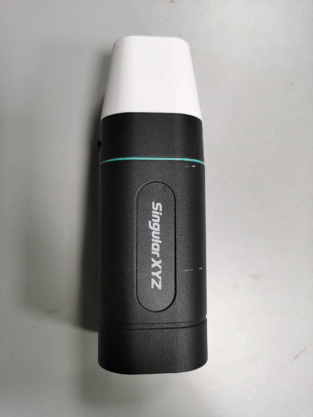
Figure 1: RTK sensor
3.2 Software
The localization data will be represented as a series of points. Since that the Faro scanner will stand on a static position while working, the points in the result forming a circular trajectory represents each working spot. In our algorithm, it firstly perform a coordinate transformation to convert the RTK data into a point cloud. Then it will repeatedly use the RANSAC method to detect circles. The distance threshold should be correctly configured to perform a proper fitting. Since that the mechanic structure of the hardware is determined, which means the proper fitted circle is expected with a radius in a specific range. Thus, we can filter the improper fittings according to the prior data. Finally, it will convert the point cloud of the result back into the RTK data.
4. System Evaluation
During scanning with Faro, we obtain precise positioning information. Each scan yields a point cloud map of the surrounding area. In one scenarios, by conducting multiple scans, we can stitch the individual maps into a larger, comprehensive 3D point cloud map. The accuracy and smoothness of the final cloud map serve as indicators of the project's success. We will test in various scenarios to ensure adaptability across different environments.
5. Result
5.1 Hardware
Initially, we planned to use a wired dGPS, which required addressing issues related to power supply and data transmission. However, in subsequent research, we discovered standalone dGPS devices, which shifted the challenge to how to securely mount the dGPS onto the Faro scanner so that it could rotate together with the scanner. To achieve this, we needed to meet three conditions: First, the mounting device had to be detachable to facilitate disassembly during transportation. Second, the position of the mount had to be consistent each time to prevent interference with our positioning algorithm. Third, the mounting device should not interfere with the operation of the Faro scanner or obstruct its field of view.
Since the Faro scanner's platform features two prominent raised stripes, we planned to use these stripes for alignment. Specifically, our mounting device would include special components that could align with a part of the stripes, ensuring that the device could be mounted in the same position each time. Additionally, to ensure the strength and stability of the device, we added a lower section and secured it with four screws. For the dGPS mounting, we designed two platforms: the first platform is the base, used for connecting and securing the dGPS base. However, to prevent shaking that might occur during rotation, we added a top platform to stabilize the dGPS receiver and prevent it from affecting the final results. The final presentation and the assembled effect are shown in the figures.
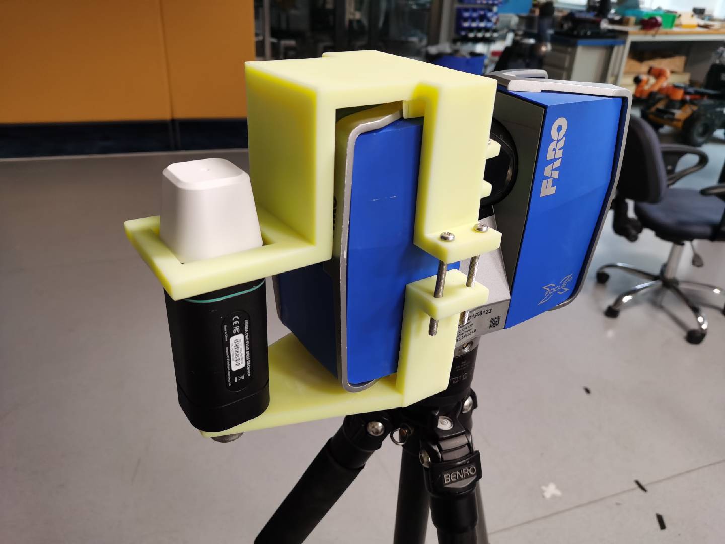
Figure 2: Carrier version 1
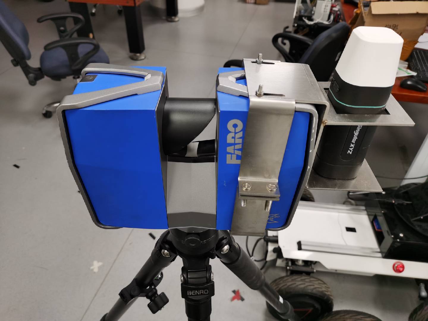
Figure 3: Carrier version 2
5.2 Software
Depending on the condition of the specific task, some parameters need to be configured again to improve the performance. In the test, our algorithm provided good results. Here are some example images. In the images, the blue points are the original data and red points are the centers of the circles.
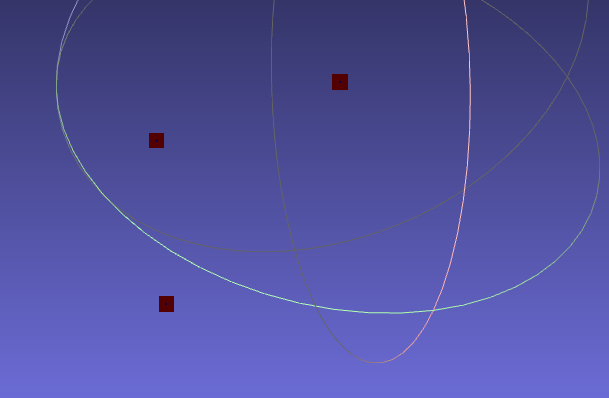
Figure 4: Result of 3 positions
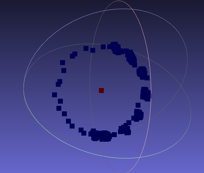
Figure 5: One of the 3 positions
6. Conclusion
In this project, we employed a RTK sensor on the Faro scanner to complete the localization task. We designed a carrier to carry the sensor. During the scanning process, the sensor will rotate with the scanner and result in a circular trajectory. We designed an algorithm using PCL to process the RTK data and calculate the position of the center of the circle to find the position of the scanner. In the experiment, we found that our first version of implementation might affect the sensor performance. Thus, we modify the structure and also the material to improve the performance. In the future, according to the requirement of the specific mission, we may have to configure several parameters or even implement more filtering algorithms to ensure the accuracy.
Generated based on the document "moma2024project-Faro.pdf".