A project of the Robotics 2020 class of the School of Information Science and Technology (SIST) of ShanghaiTech University. Course Instructor: Prof. Sören Schwertfeger.
Jiaqi Yang, Cangli Yao, Ruixiang Cao
Abstract
We try to design an auto-aiming system mounted on AGV with limited computational resources. Some visual sensors and IMU can be mounted on it. We use computer vision algorithms to do localization. And we also want to implement a robust and accurate fire control system based on a PID controller.
Introduction
RoboMaster is a shooting-based robot competition where teams could defeat their opponents through dealing damage to their robots, which, according to the game rules, can only be done by shooting at the armor modules of the opponents. Various techniques have been introduced since the first competition to boost robots’ speed and acceleration and to escape manual aiming. Therefore, robots need an real-time auto-aiming system to assist operator hitting enemy’s armor as accurate as possible.
System Description
Localization & Target Detection
We detect the target in the video frame and record the information from coding wheels or IMU if exists to calculate the relative pose and our vehicle. (If we have ranged sensor, we can just get the depth estimation directly.)We can detect the target in the frames, then the target position can be back projected to 3D space according to correspondences and epipolar geometry. In-frame detection can be done by some native methods (Haar Cascades) or even machine learning-based methods (e.g. YOLO, EfficientDet), and allthe detection algorithms are able to perform in real time. In detection part, the pattern we need to find has some features(one printed number and two light bars).
Prediction
According to the pose and structure from tracking module, we can apply Kalman filter to do the simple prediction of the possible position of target for delay issue. Furthermore, it is also possible to leverage LSTM and KNN to predict the motion of targets (refer to CS239 Report: Target Tracking with Kalman Filtering, KNN and LSTMs).
Control
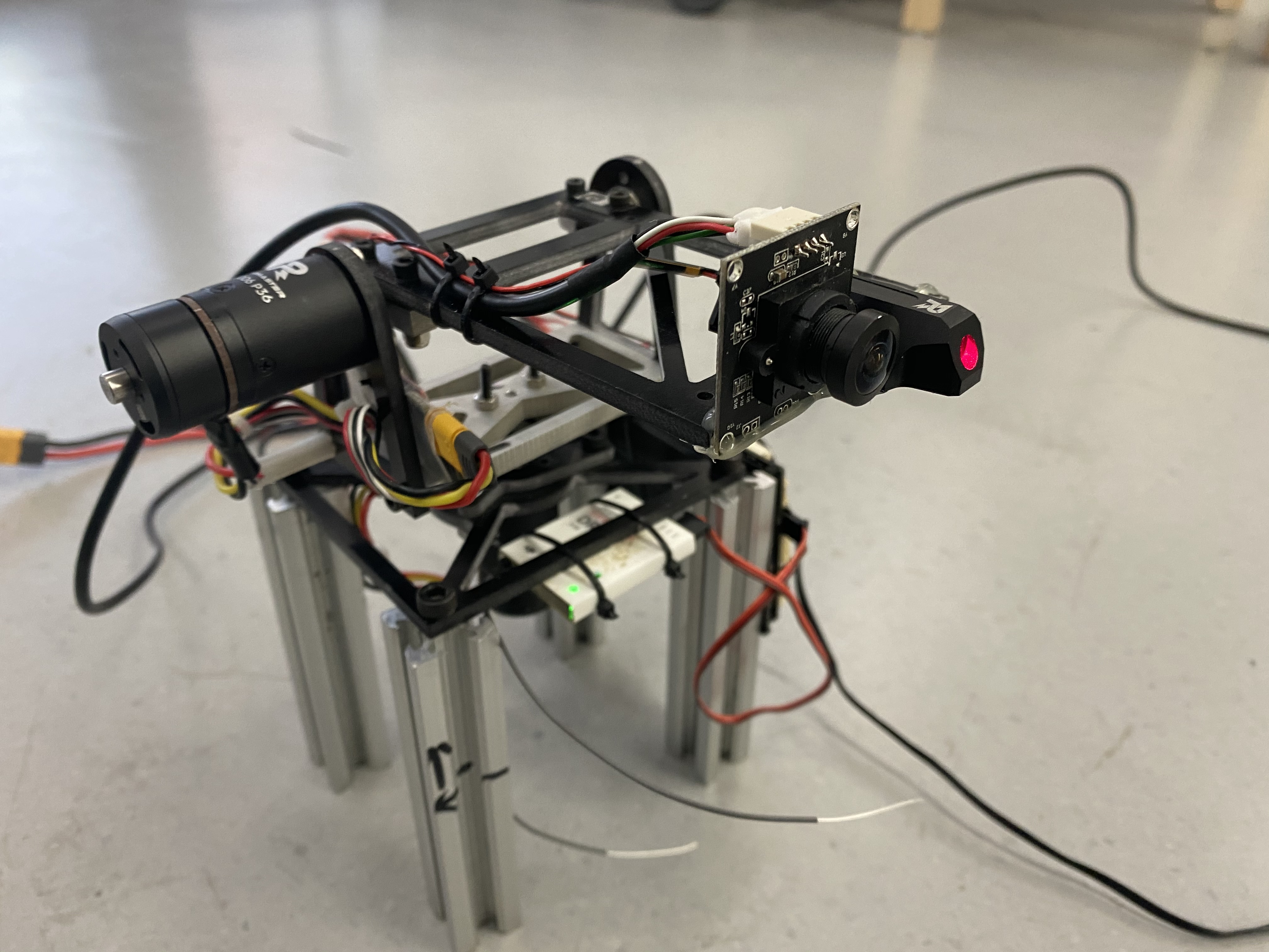
Suppose Tracking and Prediction module work, then the control module is just a simple dynamics problem. Maybe PID controller is just enough. Eventually, we may estimate the confidence of success hitting for each possible target, and decide which one to shoot automatically. Remote signaling from the operator is also required, as we need to control whether the robot should shoot or not. During the testing, we found it hard to run our program on real robot for survival reasons. Firstly,there are only two robots in RoboMaster’s lab and their team also needs them. Secondly, testing on a full functional robot will make it hard for us to run wires for our system because of the complicated mechanisms on it.In order to test our control code and algorithm more comfortable, we built a small scale test platform. It is composed of two 2006 brush-less motors and a simple carbon fiber frame. It’s the minimum configuration for us to test our program and we can easily install cameras or sensors on it to do any experiment we want.

After successfully configure the motor and the laser, we added the camera to the gimbal and use hot glue to make the laser pointing at the center of the image of the camera. The hardware part communicate with the computer through a USB cable. We use CP2102 module as a UART to USB converter. One end of it is connected to the UART6 port of the develop board and the other end is connected to the computer. In order to debug the system more conveniently, we added a remote control function.
A remote controller is linked with the develop board through a receiver. We can then control the gimbal manually with the joy stick on it. The system can switch between auto tracking mode and manual mode by changing the position of the switch on the top-left corner of the remote controller

Software
In our project, there are 2 ROS packages, one named infantry base, which bridge the gap between serial and ROS communication, the gimbal can get and set pose information from this node. The other name controller is our PID implementation for the gimbal, it get feedback from ros-topic and send control information.
The control part of the system is divided into two separate parts, the firmware of the control board and the motion controller package in the computer. The control board and the controller communicate by serial port via a single USB cable. The controller package receives the target position in the image and calculates the control command needed to get to that position using PID algorithm. Then it sends the control command to the control board via serial port. The format of the serial message is defined in the firmware of the controller board. The PID algorithm is used both in the controller board and the controller package. The controller board used PID to precisely control the motor to desired speed. The computer used PID to make the center of the camera precisely overlap with the target.
Results
We train the deep neural network by the collected datasets, and have important real-time and accurate detection algorithms. With a accurate bounding box and the known size of the robot armor, we can get the accurate depth of the target.

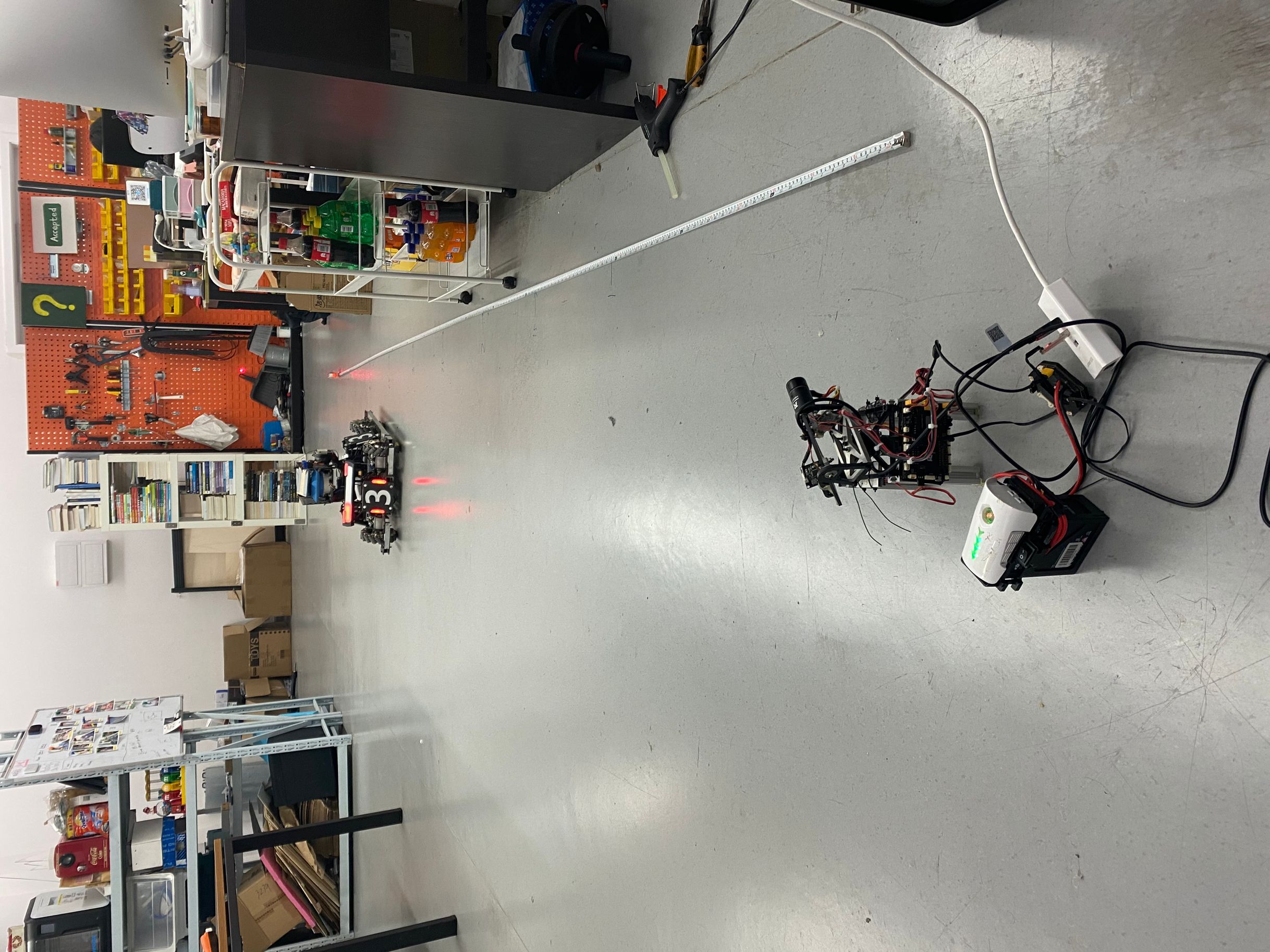
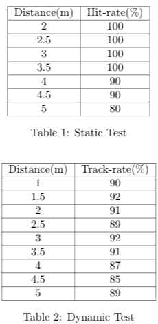
We tested our system in a indoor flat environment with artificial lighting. The target is a Robomaster robot with standard armor board configuration. The distance between the robot and the system is from 2 to 5 meters.
Video