A project of the Robotics 2017 class of the School of Information Science and Technology (SIST) of ShanghaiTech University. Course Instructor: Prof. Sören Schwertfeger.
Zhengjia Huang, Zhonglin Nian, Ning Bi
Introduction
Simultaneous Localization and Mapping (SLAM) has drawn significant interests in robotics community, as it enables the robotic vehicles to be deployed in a fully autonomous way for various applications. Recently, more and more researchers have looked towards performing SLAM on mobile robots in fully 3D, indoor and outdoor environments. 3D SLAM can be used in some pioneering systems such as rebuilding the map of an area after earthquakes and also contribute to the navigation systems on autonomous driving cars. And Lidar, due to its high accuracy in 3D range data perceiving, could be a capable sensor in SLAM work flow.
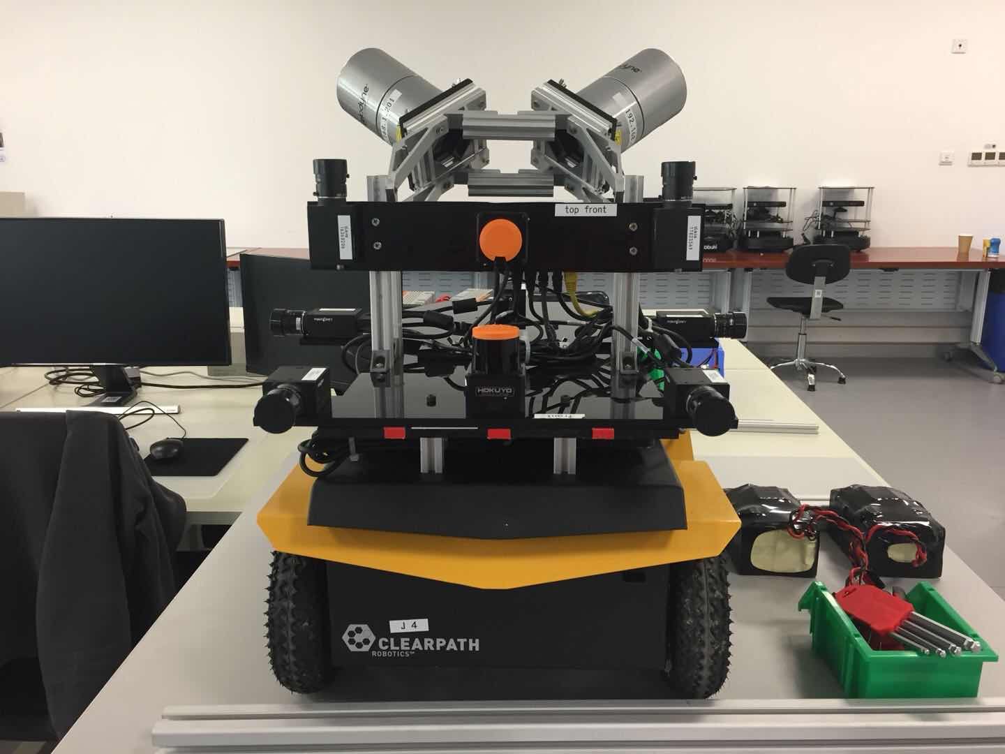
Most of the SLAM algorithms, such as the one by F. Aghili, use IMU as part of their localization unit. In this project, we tried to do 3D SLAM using two tilted lidars without IMU. Figure. 1 shows the STAR Lab Mapping robot, that we named ”Pucca”. Our work mainly built upon the Erik’s BLAM package. We tested our system in a relative small scene (ShanghaiTech STAR Lab) and a relatively large scene (ShanghaiTech SIST lobby). The result shows that our system can build accurate omnidirectional 3D map on a real time bases using two tilted lidars.
Our contributions are four-fold. First, we calibrated the two lidars mounted on our Pucca robot. Second, we figured out the pipeline of BLAM algorithm and wrote a document for it. Third, we enabled the BLAM algorithm to do SLAM using two tilted lidars so that it can build a 3D omnidirec- tional map. Fourth, we programed a node to visualize the ICP process between two closed loop laser scans to ease the debugging.
System Description

As shown in the figure abovs, the system mainly contains 5 parts. The two Velodyne Lidars scan the environment. The PCL Processing part takes in the cloud points, transform and filter them. The processed point cloud is then input into the Localization unit, which estimate the robots current pose using the current scan, previous scan, and the current map. Then, if the current frame is a key frame, the Loop Closure unit check for loop closure between current frame and previous key frames and recalculate the poses if needed. Finally, the mapping unit insert current scan into the map base on the estimated current pose. Below we describe each unit in detail.
PCL Processing
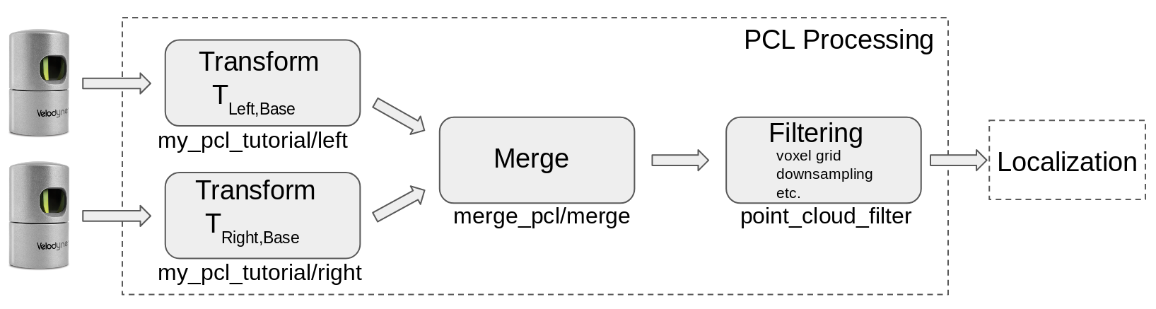
The PCL processing procedure is shown in the picture above. When doing SLAM using both lidars, two Transform nodes will transform the pcls from their lidars bases to the base link of the robot. Then, a Merge node concatenates the transformed pcls using approximate synchronizer. Our lidars are rotating at 10Hz, so the merged two pcls will have a time difference no larger than 0.05s. If we are doing SLAM using only one lidar, only the lidar and its corresponding Transform node will be on and the merge node will not run. The final step is Filtering. Voxel grid with adjustable resolution and random downsampling (90%-98% drop rate) are performed to reduce the size of point cloud.
Localization
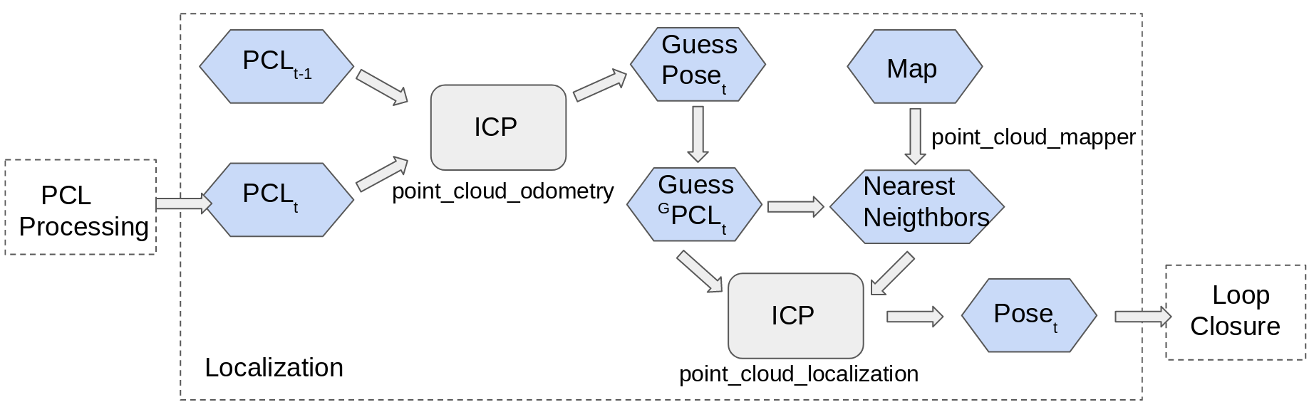
To locate the robot, the algorithm first take an initial guess based on current laser scan and last laser scan. It performs Generalized ICP between the two pcls to calculate a transform from last frame to current frame. Using the transform, we can transform the current pcl into global frame. Then, the nearest neighbors of current scan in current map are found. After that, the algorithm performs ICP between the scan and its neighboring points to get another transform, which is a correction transform of the initial guess. The final step is to compose the correction transform with the initially guessed pose to get the estimated current pose of the robot.
Loop Closure
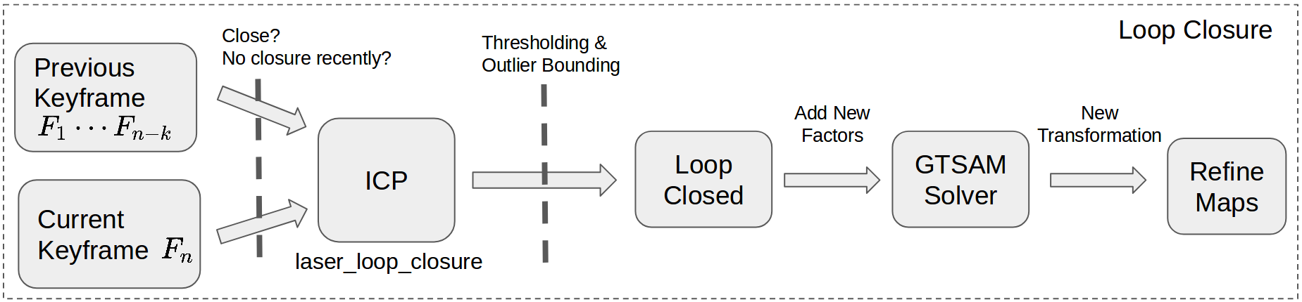
BLAM uses GTSAM for factor graph SLAM. An example is shown in the figure above. The factors are transforms calculated from ICP using laser scans of two poses. For some of the poses (Keyframes), their corresponding laser scans are stored for loop closure and mapping. To register a new keyframe, the robot has to be at a pose that more than 0.5 meters away from the previous keyframe pose. When a loop closure is detected, the poses are recalculated and the map is rebuilt using the new poses.
To check for loop closure, the current frame has to be a keyframe. Loop closure is checked between current keyframeand all the previous keyframes. For a closed loop, the following conditions have to be satisfied: (1) last closed loop happened more than 40 frames ago (2) the two keyframes are at least 40 frames away from each other (3) the two poses have a direct distance smaller than 1.5 meters (4) the ICP fitness must be below a threshold. For every keyframe, all the possible closures are checked if any of them satisfied the closure conditions, new factors will be added to the graph. Poses and map will be recalculated and rebuilt base on the new graph after loop closures.
Evaluation
Calibration

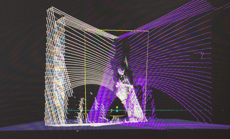
Two Lidars are mounted in two different orientations, so we need to do calibration for these two Lidars to get rigid transformations between base link and the frame of two Lidars. Instead of an accurate calibration using Lidar- Camera calibration with 3D-3D point correspondences[3], we first perform a rough calibration because the approach proposed in that paper is a simple scenario that Lidar and Camera receive almost same information from the environ- ment like stereo vision. But in our case, the camera and Lidar are mounted in totally different angles which leads to merely no correspondences. As another alternative, we put Jackal robot at the corner of walls so we could measure the alignment of two PointClouds better in RVIZ with the help of 3 perpendicular vanishing lines and two nicely mounted Hokuyo. The above figures shows our calibration setting. We tried to maximize and calibrate the overlapping of the corner scanned by the two lidars.
Mapping
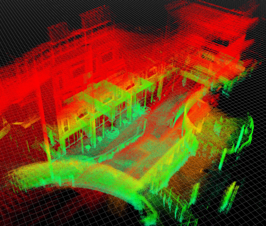

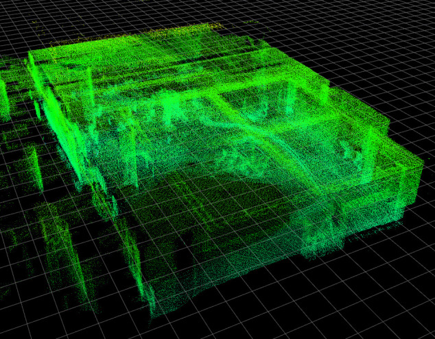
The first figure above shows the SLAM result using two lidars, while in second figure we only used one lidar to SLAM in the same scene. Comparing the results, it is obvious that the map using two lidars contains more information, such as the structure on the up-right part in the image and some of the inner structure of the room on the right part of the image. However, due to the error caused by calibration and time difference between two lidar scans, the SLAM result using two lidars is more noisy.
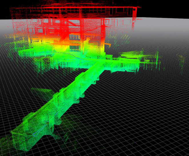

The above left figure shows a long straight corridor in SIST lobby. This it tricky for loop closure, because it has no legible features for ICP to distinguish different parts of the corridor. Moreover, due to the length of the corridor, a slight error in pose estimation will result in large discrepancy in the map, as shown in the right figure. Another challenge comes from the setting of our lidar system. Because the lidars are tilted, the view of the surrounding is limited. A lidar can only see about 45+45=90 degrees of view instead of 360 degree. So, if the robot has different rotation at the same position, the things it scanned can be totally different. This makes it hard for ICP to converge.
More results and an video are shown below

Mapping with both lidars:
Mapping with left lidar:
Conclusions
Our system can build accurate omnidirectional 3D map on a real time bases using two tilted lidars. Making the lidar tilted enables us to see the ceiling of the environment. However, it also limits the view of the surrounding of the robot and make it challenging for ICP to converge to a good result during loop closure.
Beside the contribution for now, there are some promo- tions we can work on. For example, we could figure out how to calibrate two Velodyne with the help of two Hokuyo and four depth camera nicely. Also, it’s meaningful to make use of the IMU data so that we can get better performance of localization since handling large scale laser data can be challenging for single ICP. To handle the incorrect loopclosure estimation, adding landmark can be an a good candi-date solution. Since pictures contain much more information than laser scan, we could use SIFT or perceptual hashing to compare similarity of scenes from different frames to get a better loop closure performance, or simply, attach QR codes manually in the environment as landmark.