A project of the Robotics 2017 class of the School of Information Science and Technology (SIST) of ShanghaiTech University. Course Instructor: Prof. Sören Schwertfeger.
Xiting Zhao, Yang Zhou, Jiadi Cui
Abstract
We designed and implemented perception sys- tem and navigation system of rescue robot of undergraduate RoboCup Rescue team for 2018 RoboCup Rescue Competition. We used RGB-D sensor and 2D LIDAR as our sensors of perception system which are cost-effective. We can provide 2D and 3D map and navigate in unseen environment for exploration task in RoboCup Rescue Competition.
Introduction
The RoboCup Rescue Project is intended to promote research and development in disaster rescue which is a sig- nificant domain at various levels. The goal of the RoboCup Rescue competitions requires robots to show abilities of mo- bility, sensory perception, planning, mapping, and practical operator interfaces on searching for simulated victims in unstructured environments.
What we are participating is RoboCup Rescue Robot League (RRL) competitions, and we are focusing on solving exploration tasks in this project. The exploration tasks need teams to create 2D and/or 3D map of a dark Labyrinth while traversing, recognize objects including QR codes, fire extinguishers, doors, simulated victims, and other items, avoid amorphous negative obstacles along a robot’s path, drive and map while avoiding amorphous terrain obstacles without enclosing walls. What we focused on is 2D and 3D mapping, navigation and obstacles avoiding.
To make the problem statement clear, we will describe our task in more details. The problem for 2D/3d mapping is described as below. The dark labyrinth is constructed by wooden walls without significant visual features. The labyrinth is narrow which makes it hard to get some good feature like edge and corner to match. In many cases, the camera is capturing only a wall without any edge information since the camera is too close to the wall. It is quite hard to get decent 3D map only using visual SLAM algorithm. Since most walls are vertical with respect to the ground, the 2D SLAM algorithm can provide a quite good 2D map which is also the 2D projection of walls using 2D laser LIDAR. We combine 2D SLAM and 3D SLAM together and get good 3D map.
The problems for obstacle avoiding and navigation are described as below. Since there are some obstacles in the labyrinth. To avoid complicated control of going over these obstacles, we need to avoid them. These obstacles cannot be captured by 2D laser LIDAR since we mount the 2D laser LIDAR on the top of our robot. We used RGB-D sensor to get accurate location of these obstacles and projected these obstacles onto 2D map. The obstacles avoiding problem is simplified to 2D navigation problem. Since we can have 2D map of walls and projections of obstacles. We can just use standard 2D navigation algorithm to navigate.
Systen Description
Hardware

The Main Computer and Motor control
We use an mini PC of Intel i7-7500u as the main computer which needs low power and satisfy the computation demand of using Kinect 2.0. We use the Arduino Mega and DC motor driver to drive the motor. The Arduino Mega is connected to the mini PC and communicate with the ROS by rosserial package,and use diff drive controller package to control the movement of robot.
Kinect 2.0 Sensor
We put Kinect 2.0 Sensor in front of the robot. The RGB camera has 1920x1080 resolution, the depth camera has 640x480 resolution, the FOV is 70x60, the detection range is 0.5m-5m.
Lidar
We mount a YDLIDAR X4 on the top of our robot. This LIDAR is really cheap and is highly competitive comparing with other expensive LIDAR. The sample rate is 5000 samples per second, the original spinning frequency is 7Hz which we hacked the electronic board to raise it up to 12 Hz, the scanning distance is 0.12m- 10m. The LIDAR is used for 2D mapping and improve 3D mapping by combine 2D SLAM and visual slam together.
Calibration
We use the calibration tool to calibrate Kinect 2.0. This tool use the chessboard patterns to calibrate all the camera including RGB camera, IR camera and depth. We captured a lot of pictures to calibrate the camera about 100 pictures for each camera. After that we get some camera matrices including rotation, translation, essential and fundamental matrix. The depth quality changed a lot after calibration. To calibrate the relative location between Kinect 2.0 and 2D laser Lidar . We use the matlab toolbox for kinect calibration. After calibration, we get the relative position between two sensors, and use the vertical point as the base link and create the tf relationship between them.
Software
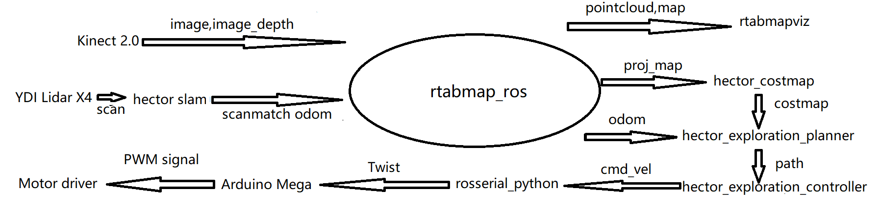

Our software is developed based on Robot Operation System(ROS) which is very popular software architecture. We use a lot of ROS package to finish the project. The pipeline is discribed in the figure. Firstly, we use iai_kinect2 and calibrated camera yaml to get the rgb image and depth image from Kinect 2.0. As the compressed image and 1920*1080 resolution need huge amount of computation, which cause the slam is very slow. As performance limit, we choose 960*540 resolution raw image, which can let us get an process rate at about 20 Hz. We also collect the laser scan data from YDI Lidar X4. While get the sensor data, we also publish tf of the sensors: laser_link and camera_link, according to the calibrated relative location. Then we use hector_slam to get the scanmatch odometry. As we didn't finish the hardware motor encoder now, we have to use the scanmatch odometry for the rtabmap_ros in the next step. In the rtabmap_ros, which is the main part of the SLAM, we use combined 2D and 3D SLAM, so we can get the pointcloud, the 3D projection map, the 2D map and the SLAM odometry. We use the rtabmapviz the visualize the map and the point cloud. After that we transform the 3D projection map to costmap to avoid obstacle in 3D. And we use the hector_exploration_plannar to plan the exploration path. Use the hector_exploration_controller the convert the path to robot velocity command cmd_vel. Use the rosserial_python to send the twist to arduino and use PWM signal and Motor driver to control the motor.
Different SLAM approach
We use Kinect 2.0 as the sensor for our 3D SLAM. We have tried several 3D SLAM algorithm including RGB-D SLAM, ORB SLAM and RTAB SLAM. And at last we choose RTAB SLAM as our 3D SLAM algorithm. After testing for several times, we realized that the 3D map built only by 3D SLAM is not accurate enough, the angle between walls will have some errors caused by drift and miss matching which often happens in rescue scene which is lack of feature. In the figure, the RGB-D SLAM get lost after some times. The ORBSLAM2 didn't matches well and drift a lot. The rtabmap use only rgbd camera is a bit better than last two but also drift near the exit.
At last, we decide to hybrid 2D SLAM and 3D SLAM together since we found that the 2D map built by Hector SLAM is good enough to guide 3D SLAM algorithm. We mounted 2D laser LIDAR on the top of our robot to avoid the influence of obstacles which will get a 2D map that is exactly the 2D projection of walls in 3D map. Hector SLAM estimate the odometry by ICP, and 3D SLAM estimate the odometry by visual approach. We use the odometry which is estimated by combining the information of 2D odometry and 3D odometry to guide 3D SLAM which gives us really good mapping result. In the figure, you can find that the wall aligned well and nearly no drift
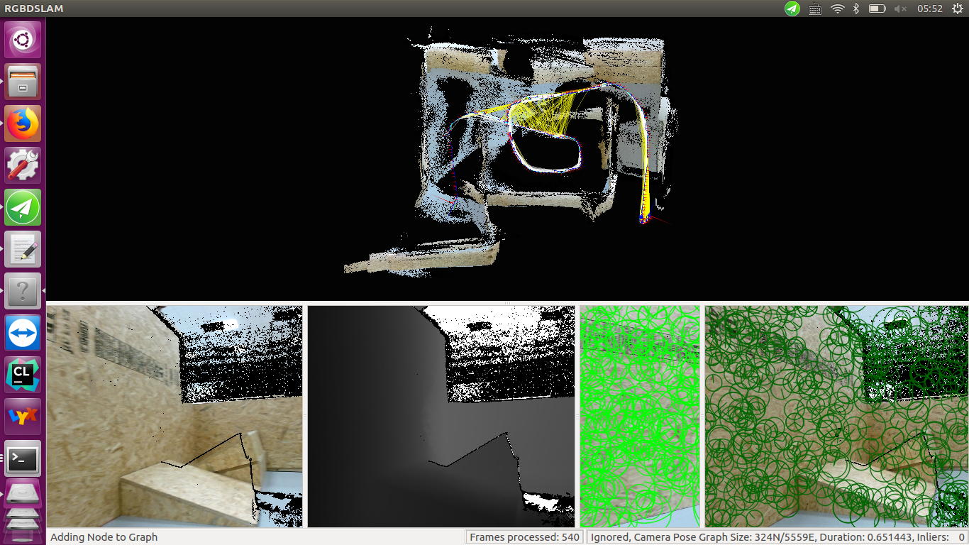
RGBD SLAM result
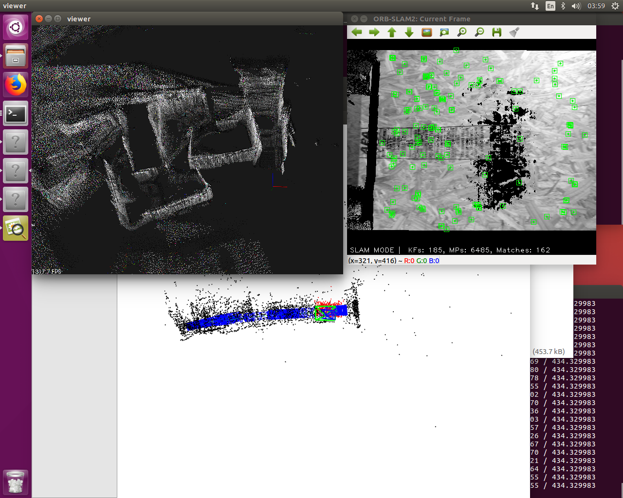
ORBSLAM2 result
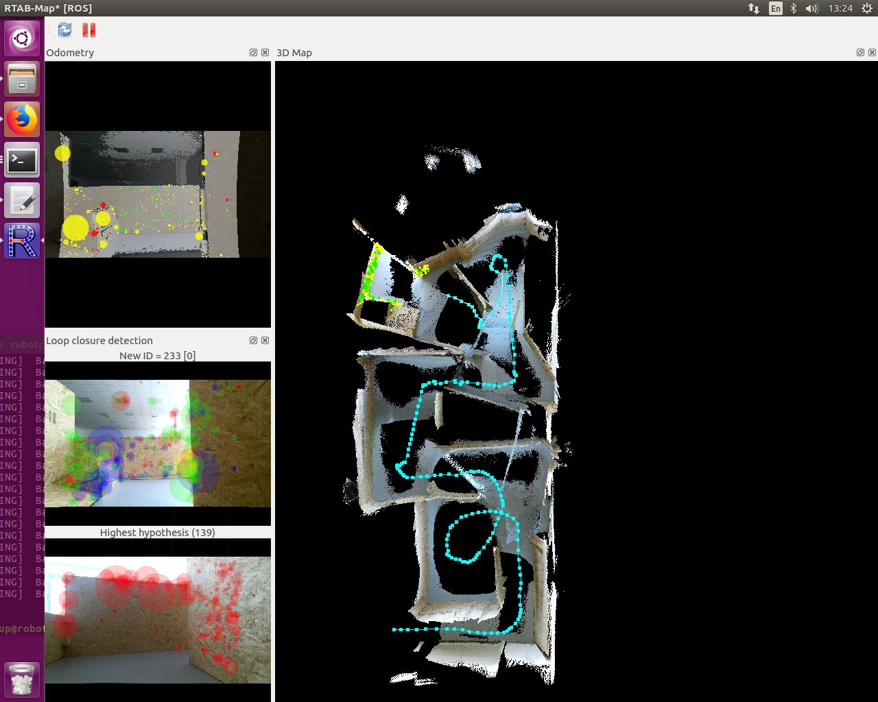
RTRAMAP RGBD only result
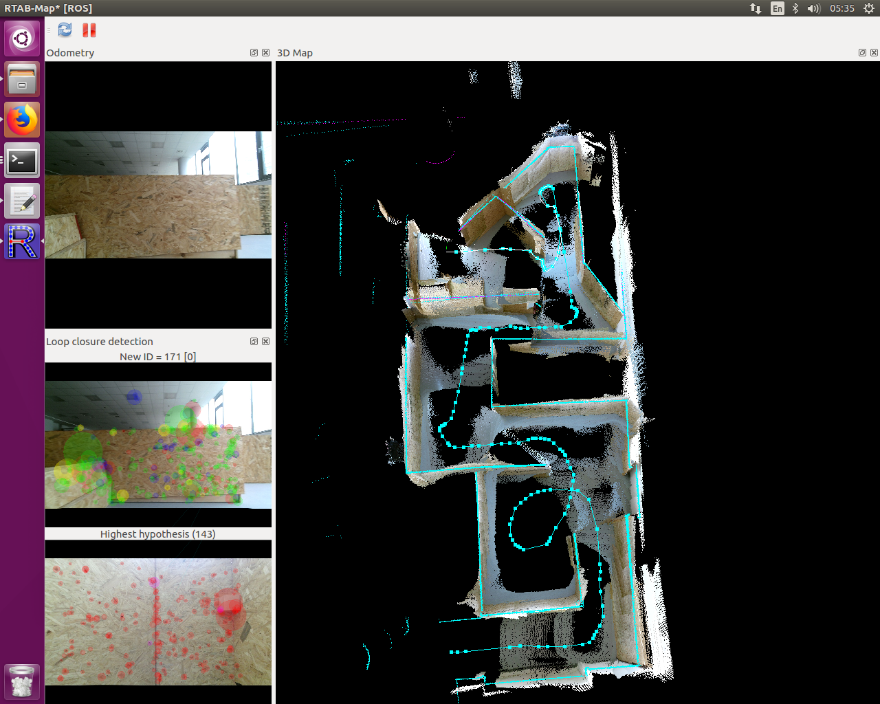
RTRAMAP RGBD with Lidar result
Navigation
We achieved navigation using ROS Package hector_ navigation. Using the 2D projection map of 3D map ping produced by SLAM algorithm, the navigation algorithm first build cost map for the exploration task, then hector exploration planner which is based on exploration transform approach presented in will start navigation.
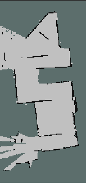
Project Map
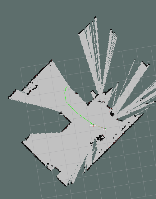
Exploration Path