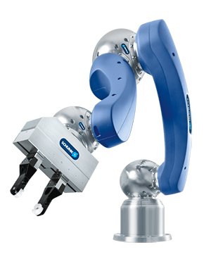
We'd like to apply the 6-axes robot arm in traditional 3-axes or 5-axes CNC machine. Traditional 3-axes or 5-axes CNC machine has many limits: 1) Most of traditional CNC machine is in a enclosed box. 2) The milling head just can move in 3-axes and the milling range is limited. 3) The robot arm can move around the object thus the object can be very large, such as a sculpture. The robot arm based CNC machine we build will be capable of doing these job.
The Robotic Arm is a programmable mechanical arm, which is mimicing the movement of human arms. The robot arm usually consists of joints and links, the number of different arms may be different. It's common to see a 5 or 6 joints robotic arm. And the links that connect joints make it possible to actuate rotation and translation. And the links are considered as kinematic chain. So we can calculate the speed and pose through different frames relative to base frame. For this project. Similar to 3D printer, the idea of 3D incision by robot arm is aimed to carve on a raw material by following determined path to create a 3D model. This requires the program realize avoiding collision, reaching around obstacles and planning divesity of points to arrive at the goal step by step. We thought this is interesting and cool to 3D print something by a robot arm, something that a man's arm even cannot do well.
Approach
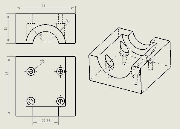
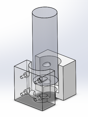
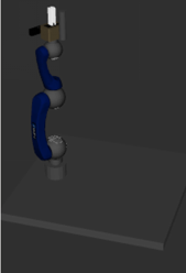
Driller and Model Calibration To simulate the real condition for Schunk arm, first step is to calibrate the model and set the collision attribute. We fisrt describe the urdf and xacro file to build the model for schunk arm in RVIZ and Moveit!. The main work is to write the size, collision area and geometry. Below is a part of prgram of the urdf, each position of link is based on the frame of its parent joint, and one joint may have multiple links, the joint and link both contains the information about their rotation and position. For links, there are shape and collision to describe, to make sure the link can be visualized in model and have collision avoidance attributes. After many times recorrect data, we finally get a relative similar model with the real one. And then, we use 3D printer to design the model to fix driller on Schunk arm. The desgin model is drawn in Solidworks, shown as below:
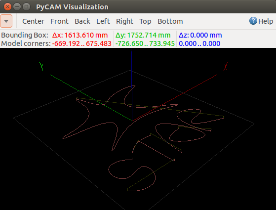
Generate the Coordinates for Carving We choose the PyCAM software to generate the path of 2D/3D incision. The software goes like below:
In this window, we can generate any shape of model as we want, it provides the reserved shape and also allow us to draw it by ourselves. Here we choose a simple pentaon as the goal path points. And we can get the raw datas and then we write a reading data program by C++. During compiling, the data type convertion and the loop time is important factor to consider. First time, we choose to generate a bag and let main program to listen to this topic, but it takes extra time, so we finally combine the reading program with main program together to save effort. With the help of this program, we input the data into program and make complicated path planning available.
Move the Arm by Moveit! MoveIt! is state of the art software for mobile manipulation, incorporating the latest advances in motion planning, manipulation, 3D perception, kinematics, control and navigation. It provides an easy-to-use platform for developing advanced robotics applications, evaluating new robot designs and building integrated robotics products for industrial, commercial, R&D and other domains. 1. We can load our schunk arm URDF file, in which LWA4P is provided from schunk CANopen driver package, and download schunk pg70 gripper. Also, we have done some change in it, that is add the camera, table and drill; 2. We can plan to a pose goal, which means we set a x,y,z and p,r,y, and execute the plan, we can also plan to a joint-space goal. But what we need in this project is cartesian path plan, because plan to a pose goal can guarantee that the trajectory is what we want, since the planner plans in the joint space, the shortest path in the joint space is always not the shortest in the world space. 3. We can plan a cartesian path directly by specifying a list of waypoints for the end-effector to go through. Note that we are starting from the new start state above. The initial pose (start state) does not need to be added to the waypoint list but adding it can help with visualizations.
Cartesian motions are frequently needed to be slower for actions such as approach and retreat grasp motions. Here we demonstrate how to reduce the speed of the robot arm via a scaling factor of the maxiumum speed of each joint. Note this is not the speed of the end effector point. We want the cartesian path to be interpolated at a resolution of 1 mm which is why we will specify 0.001 as the max step in cartesian translation. We will specify the jump threshold as 0.0, effectively disabling it. Warning - disabling the jump threshold while operating real hardware can cause large unpredictable motions of redundant joints and could be a safety issue. And the function will automatically visualize the plan in Rviz. If the visualize is in our expectation, we can execute the plan.
Experiment and Result
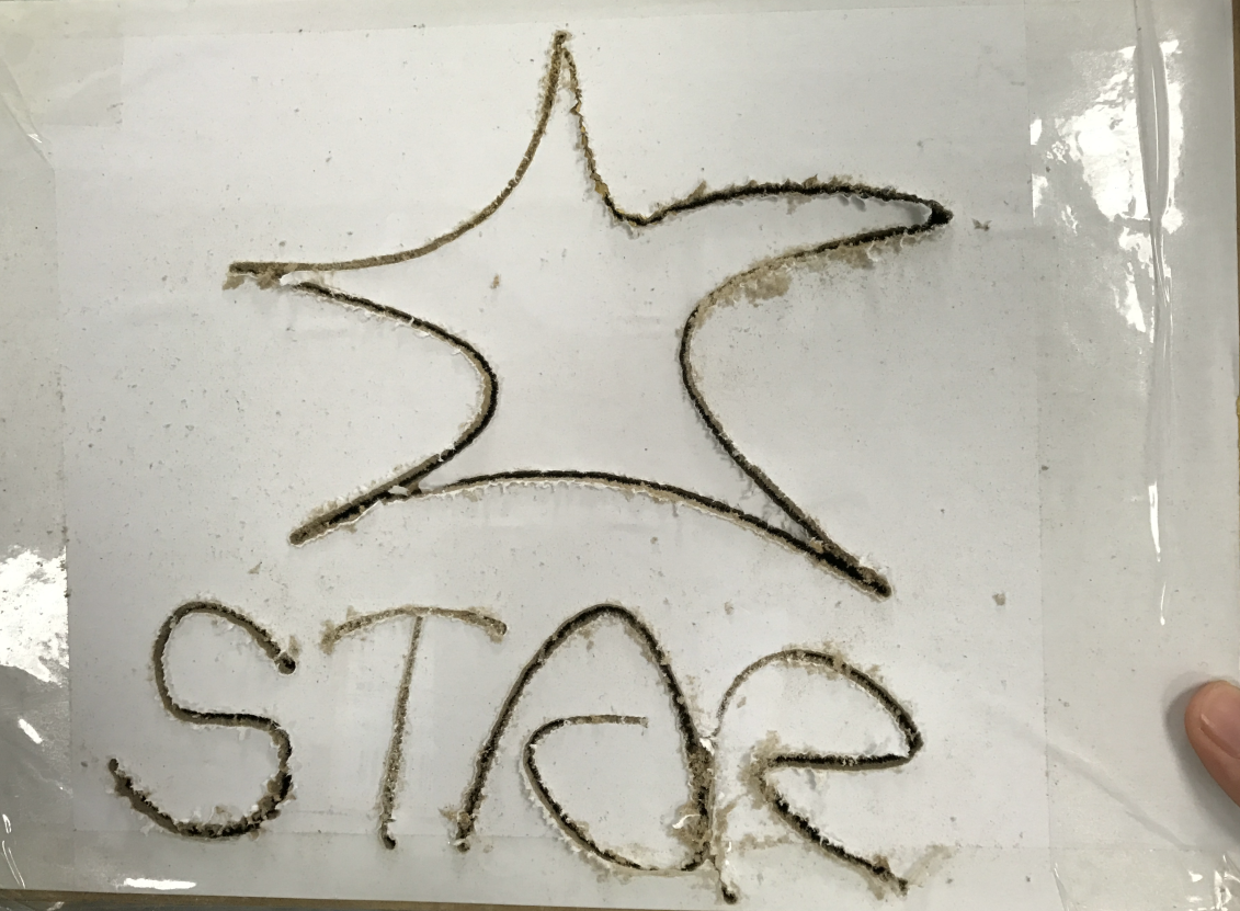
Our system is maily aimed to build a robot-arm based 5 or 6 axes CNC machine. It consists of 3 parts: 1.Model building: We need to build up mathematica model to show the trasformation and rotation among different joints. 2.Motion planning and g-code generate: we try to build up a bridge to take the use of G-code, which is highly integrated and easily to control 3D printer, so that the motion planning can be realized at the same time. 3.Arm execute: just apply it and check and recorrect the error! We finally adjust the algorithm to make sure that everytime the exectution is 100\% successful, and there is no missing point or path in pratice. However, because of the limitation of velocity, Schunk arm does not completely goes in average speed as we expect. Here is an example we draw by schunk arm:
Here is a video for our project:
Conclusions
In conclusion, our team firstly focused on 2D incision, and the main problem was to build a mathematical model, which contains relationship between different frames. Then based on each servo motors' rotating ability, we applied the model and motion planning method into program, then we kept repeating test till it works well. In those processes, we three students learned the knowledge about ROS system, Robot Arm and how to program to manage path planning. Also, we develop the ability of team work. Finally, we want to show our thanks to professor Soren Schwertfeger for giving us much help in our project, offering us a very nice introduction to the robot arm, and providing us with so nice hardware Schunk, Xtion and ohter equipments. And he patiently teaches us a lot from scratch. We also thank our University for providing us so nice place to study and do experiments.